5.1. Infrastructure View
5.1.1. Views
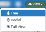
On Top right corner, click on the View > Tree to see the Tree View.
Change Infrastructure View

Topology - Infrastructure (Tree) View
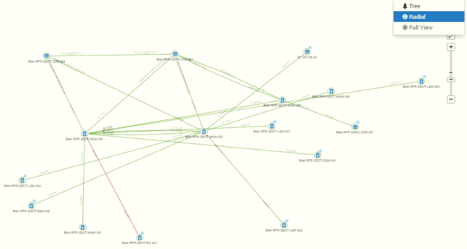
Topology - Infrastructure (Radial) View
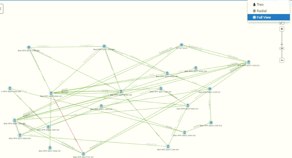
Topology - Infrastructure (Full) View
Note
In full view, all the devices under parent node will be visible, whereas in Tree and Radial view, the nodes which are under two hops i.e.(Node 0, Node 1 and Node 2) will only appear.
5.1.2. Topology Information
Click on the on top right corner to see the details of the topology information.
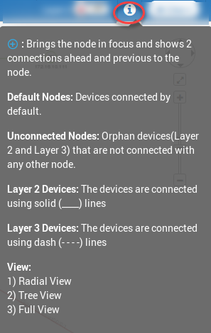
Topology Information
Keep the cursor on the branch of topology and you’ll see details of connected nodes.
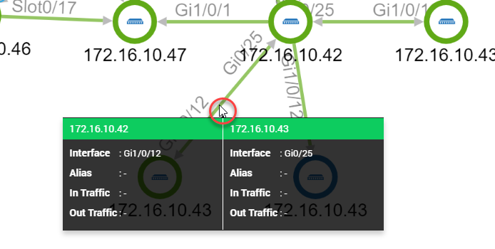
Branch Showing Details of Connected Nodes
5.1.3. Enable/Disable Layer 3
Toggle the layer - 3 switch in top right corner to see the Layer - 3 connectivity links.

Layer 3 Toggle Switch
When the end points of the topology link are Layer 3 switches, the diagram shows dotted connectivity between the two.
When the end points of the topology link works as both: Layer-2 and Layer-3, the diagram shows dotted and solid connectivity between the two.
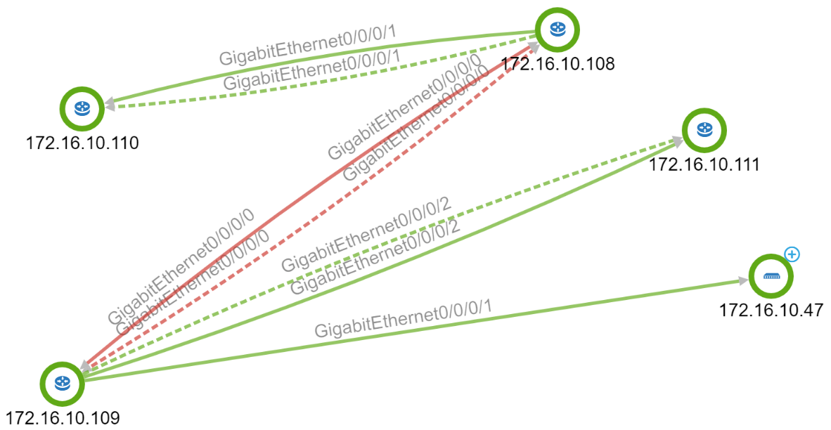
Layer 3 Connectivity
5.1.4. New Node
Create a new node. Basically you are creating a category/group. You can link default and unconnected nodes to this created category/group node. The linked nodes will display in hierarchy under the node you created.
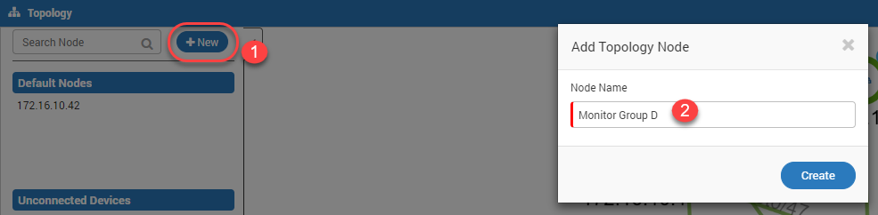
Create New Node
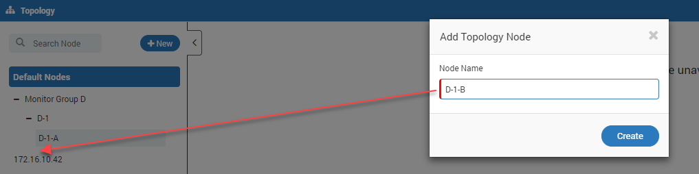
5.1.5. Create Multiple Hierarchy
You can create multiple level hierarchy of your nodes. Right click on the node you created and click Add button.
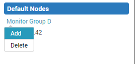
Add Child Node under the Node - ‘Monitor Group D’
Child Node goes under Respective Parent
5.1.6. Default Nodes
Default nodes are the center of topology. Some properties of these nodes are:
IP addresses you selected while creating scheduler job.
Clicking on node shows topology around it.
The topology will show 2 connections ahead and previous to the node.
If there is a ring topology available in above 2 nodes, all the nodes of the topology will be visible.
For additional nodes (connections ahead of 2nd node), there is a plus (+) button.
Click the button and topology (with concerned node at center) will show up.
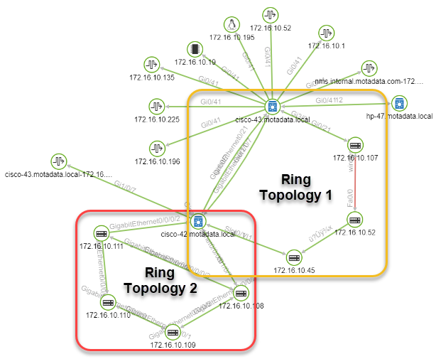
Ring Topology
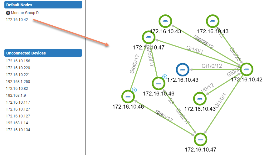
Default Nodes and its Topology
5.1.7. Unconnected Nodes
The nodes under this heading are orphan nodes that are not connected with any other node.
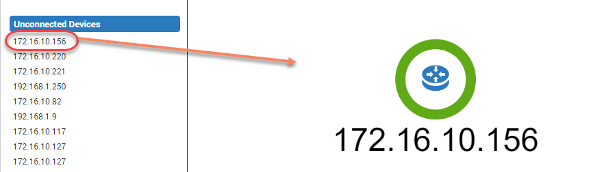
Unconnected Nodes
5.1.8. Link/Unlink Nodes
Right click on any default or unconnected node and select ‘Link Region Node’.
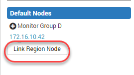
Link Node to a Region
You can Link other nodes by Clicking on the devices.
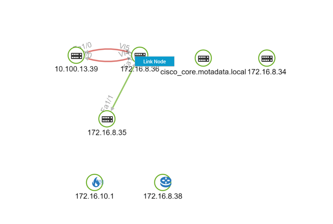
Link Interface
Here, while selecting the source interfaces, only 1 single interface at a time can be selected. Multiple selection is not allowed.
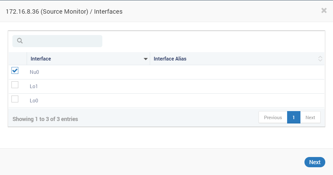
Source Interface Link
After that, you can select the source Monitor for the selected device. And Click on link to see the connectivity.
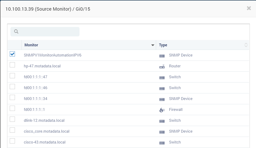
Source Monitor selection
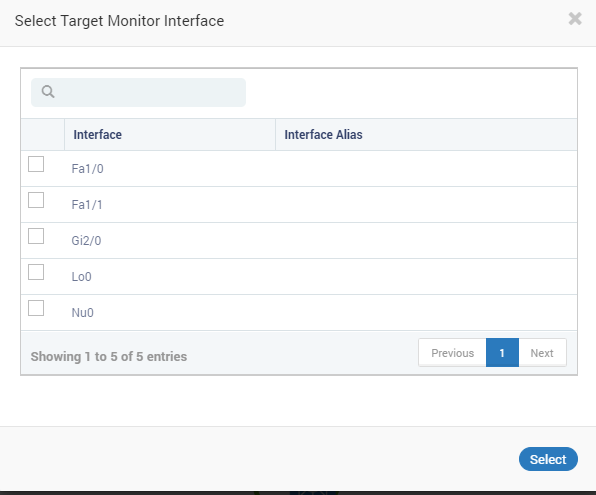
Target (Destination) Monitor Interface
Thus a link with the selected monitors would appear as in the diagram.
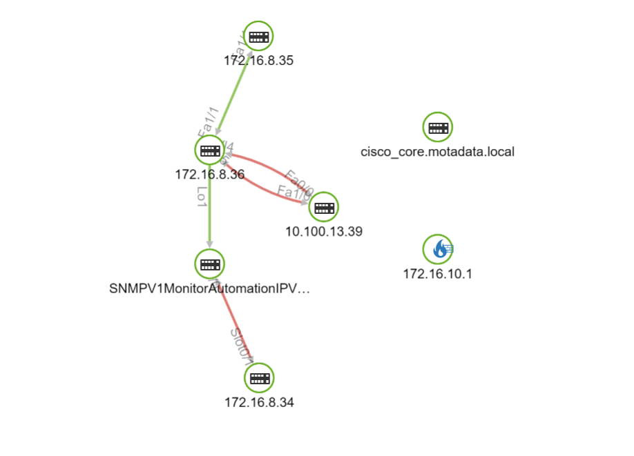
Linked Nodes
You can now unlink node interconnections as shown in the diagram. Right click on the interface and select unlink node.
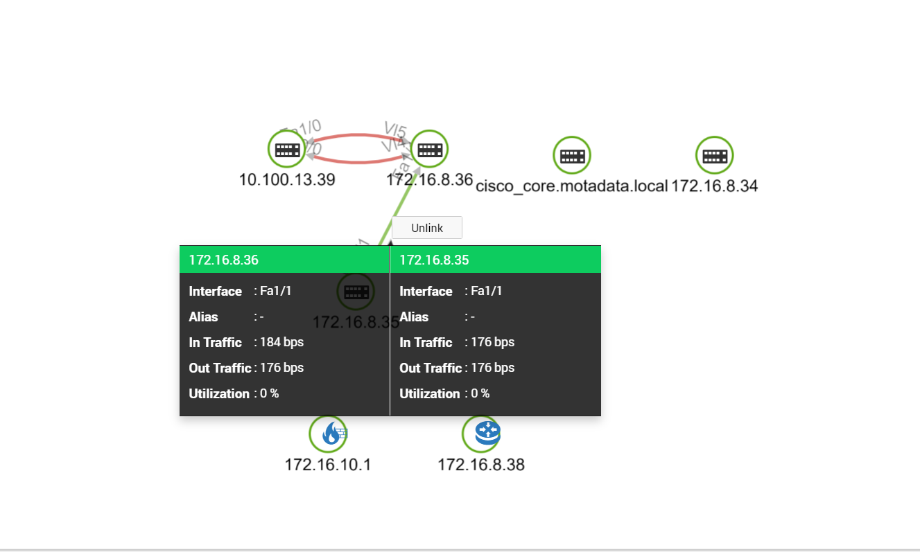
Unlink Option in Topology Diagram
Note
While selecting any nodes, only the unused interfaces would appear in the list as you can link only one interface at a time.